Design system study
Parametric Mechanisms
Six printable product studies spanning equations, configurable geometry, surfacing, functional mechanisms, and rapid problem solving.
- Period
- 2024–2025
- Role
- Independent designer and fabricator
- Methods
- Parametric CAD · FDM · Mechanisms · Design for Assembly
Engineering Challenge
Build printable products whose geometry could change without breaking design intent, then reconcile mathematically clean CAD with the less predictable behavior of flexible materials, clearances, layer orientation, and real hardware.
Approach
Across six studies, I drove critical features from named dimensions, equations, patterned geometry, surfaced master models, and measured interfaces. I reverse-engineered existing products, printed functional prototypes, and fed fit, stiffness, process behavior, material research, and fabrication results back into the models instead of treating the first CAD solution as finished.
Results
The six projects became practical studies in design intent, compliant features, print clearances, configuration management, surfacing, validation boundaries, and speed. The replacement watchband progressed from an overly stiff first TPU print to a curved, wrist-worn second version. The can-lid study reinforced that a functional prototype is not automatically safe for its intended use, while the sink-caddy retainer and printed glider showed how the same parametric workflow can scale from a two-hour household fix to a complex aerospace-inspired form.
Start With the Hardware That Has to Fit
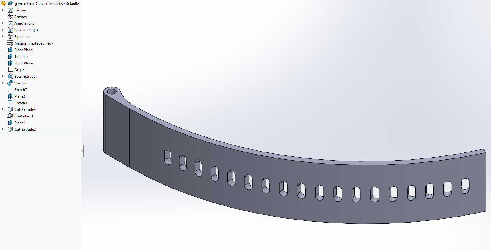
After the original Garmin Vivoactive 4 band broke, I measured its attachment and pivot geometry with digital calipers. The first SOLIDWORKS model used equation-driven dimensions, extrudes normal to their sketch planes, and a linear pattern for the adjustment holes. That simple version established the interface and overall size before I invested in more complex geometry.
The Right Thickness Was Still Too Stiff
For the first TPU print, I reduced the top and bottom layer counts and changed the infill direction and pattern in PrusaSlicer to encourage flexibility. The result matched the original band's thickness but was much too stiff because the printed material and structure behaved differently. That failure redirected the second version toward a thinner section and an intentionally curved resting shape.
Control Length, Spacing, and Print Behavior Together
I retained a straightforward extrude around the pivot, then built the main body as a sweep. Dimensioning the path by arc length preserved the required overall band length, while a curve-driven pattern kept every adjustment hole evenly spaced and correctly oriented along the bend. The curved geometry required a new print orientation, so I added a brim for the small first-layer contact area and set the band to exactly three perimeters thick for flexibility without unnecessary infill. Despite the risk of the tall TPU print flexing under the toolhead and causing layer shifts, the second version printed successfully and completed four weeks of wrist use without problems at the time of the video.
A Functional Fit Still Needed a Safety Decision
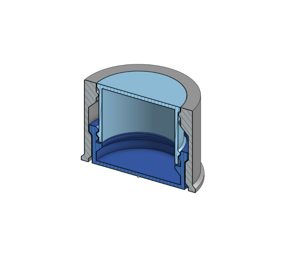
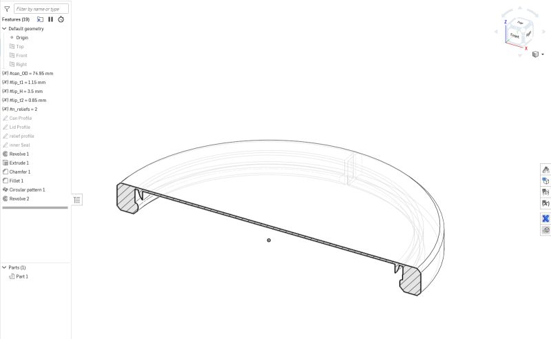
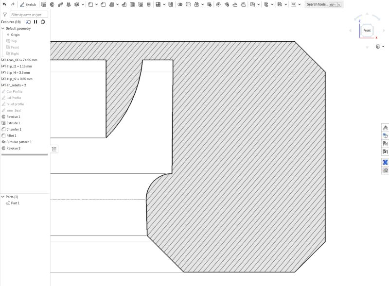
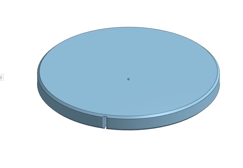
I designed a flexible TPU lid to replace the disposable foil I was using on opened cans. Consistent can diameters and the rolled rim provided a clear interface for retention, and the CAD study combined a thin flexible membrane with a snap-over perimeter. Before using the prototype for food storage, I investigated the full manufacturing context. FDM layer lines are difficult to sanitize, TPU is not compatible with acetone vapor smoothing, dyes may introduce additional concerns, and a brass nozzle can create a potential lead-contamination risk. With those issues unresolved, I retired the printed concept for food use and chose a commercial food-safe product instead. The result was still valuable: intended use and process safety are design requirements, not checks to add after the geometry works.
From Daily Friction to a Printed Fix in Under Two Hours
The existing sink caddy had a simple but frustrating failure mode: even a minor adjustment could knock the brushes over. I used Onshape to develop a snap-on retainer around the existing caddy, then printed and evaluated multiple versions on my Prusa. The final part restrains the brush handles without replacing or permanently modifying the original product. Moving from the observed problem to the finished solution in under two hours made this a compact example of rapid CAD iteration, interface design, and additive manufacturing applied to everyday life.
Equation-Driven Surfacing, Then a Complete Physical Build
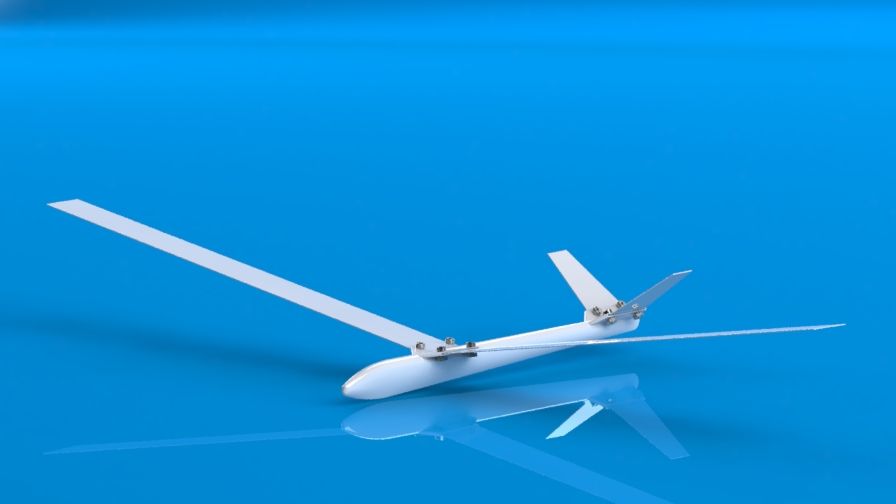
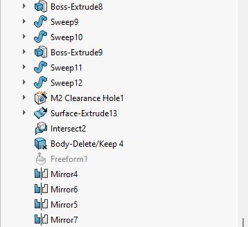
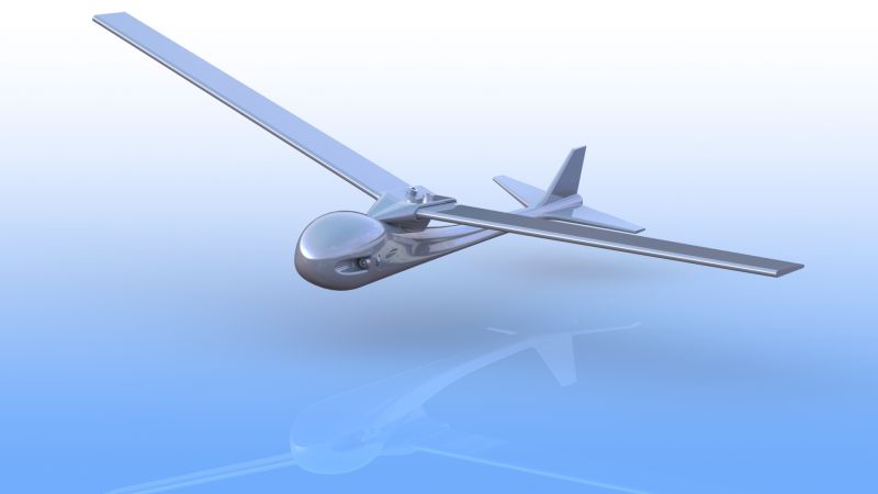
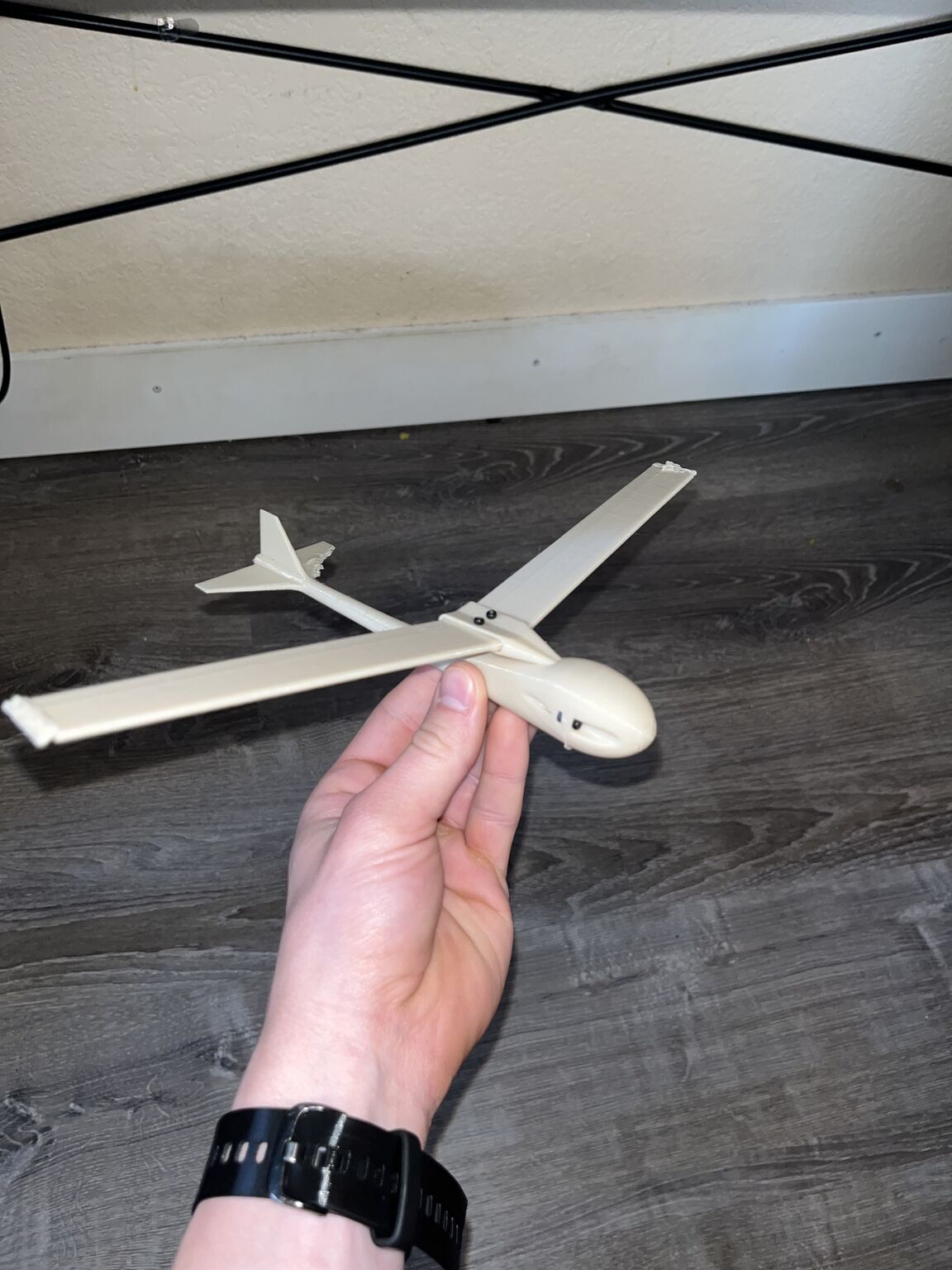
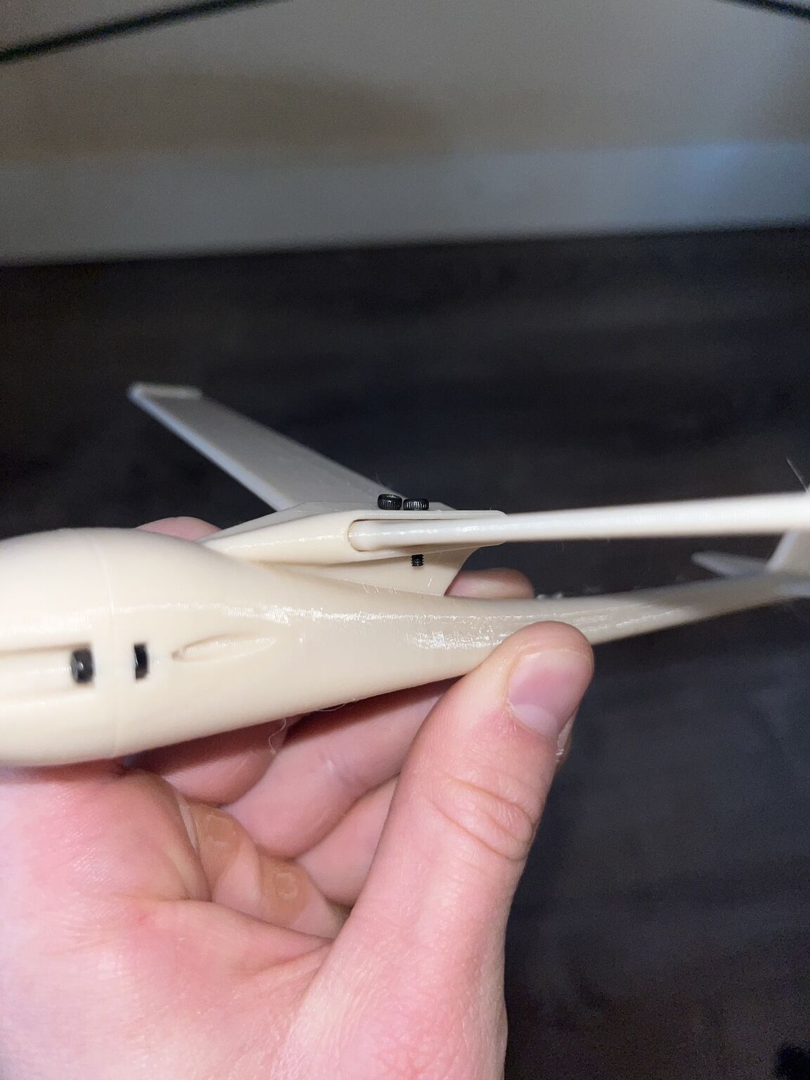
I began this glider as a focused SOLIDWORKS surfacing exercise and used a master-model approach to control the complete airframe. Global variables and equations linked the fuselage, wing, and stabilizer proportions, while a deliberately organized feature tree coordinated the surface lofts, fills, trims, knits, mirrors, and solid features needed to produce printable geometry. I also drew on prior aerospace coursework while shaping the configuration with the goal of making a functional glider. The project progressed from the parametric CAD model to a final render and a complete 3D-printed assembly with removable surfaces and small mechanical fasteners. The posts document successful fabrication, but not verified flight performance, so the result remains a surfacing, master-modeling, and print-integration study rather than a validated aircraft design.
Key Outcomes
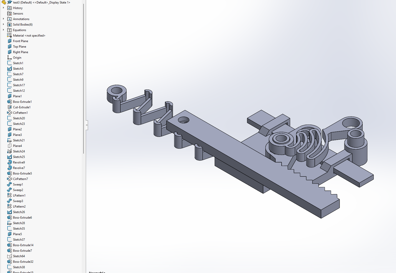
- Parameterized spring coils, tooth geometry, wall thickness, and hardware
- Reverse-engineered the Garmin Vivoactive 4 interface with digital calipers
- Used arc-length dimensioning and a curve-driven pattern to control watchband length and hole orientation
- Turned a failed TPU stiffness test into a thinner, curved second version
- Designed seamless print-in-place and puzzle-like interactions
- Stopped a functional can-lid concept after research exposed unresolved food-contact risks
- Designed, iterated, and printed a snap-on sink-caddy fix in under two hours
- Built an equation-driven glider master model, render, and complete printed assembly
Sink-Caddy Retainer Demonstration
The original demonstration shows the brushes falling during small adjustments, followed by the snap-on retainer developed through multiple Onshape and printed iterations.
Related Links